Using IM Flows
Design a Flow model based on correlations
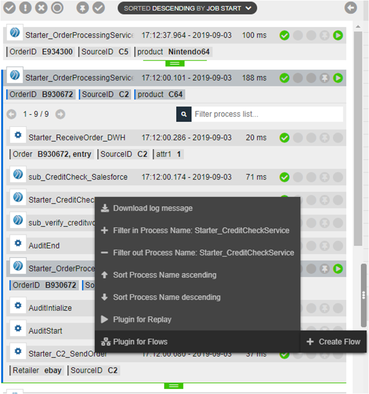
If you already have correlated processes in nJAMS, you can create a Flow automatically based on a list of correlated processes. To create a Flow model, enter main view in nJAMS GUI and right click on any of the correlated process instances in the Reslst list. Select “Plugin for Flows > Create Flow”:
After assigning a name for the new Flow, the flow editor will open a computed model, using the Correlation Log Id and Parent Log Id of the correlated processes:
Start and end rules are created automatically. Please validate the generated rules and modify the rules, if applicable.
Design a Flow model from scratch
Start with the creation of a new Flow model:
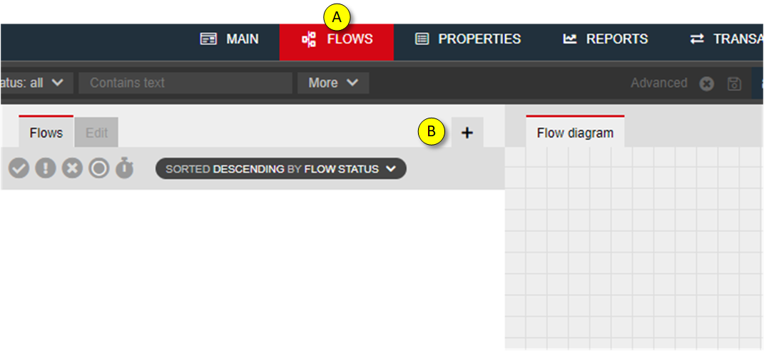
- Enter tab “Flows”
- Click on “+” to create a new Flow model
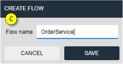
- Enter a name for the Flow model and click SAVE
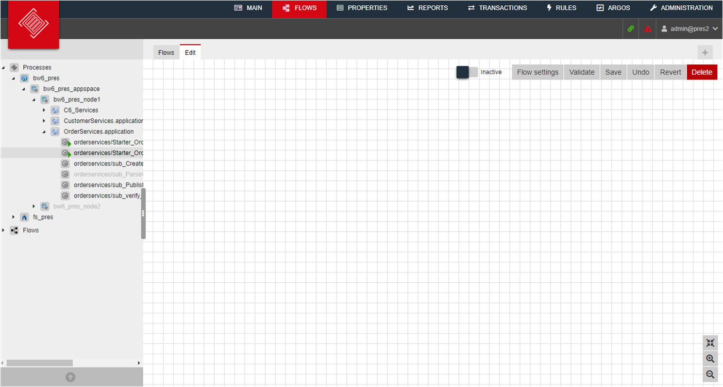
After creating a new Flow model you will get a blank model pane:
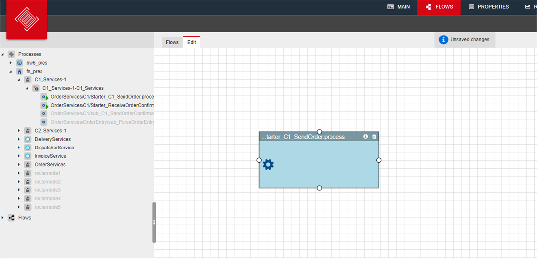
Select an element from Tree and drag the element into the pane on the right hand side. Release the mouse button and IM Flows creates a new step:
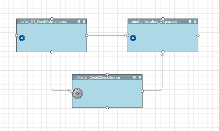
Continue to drag in all steps for the Flow:
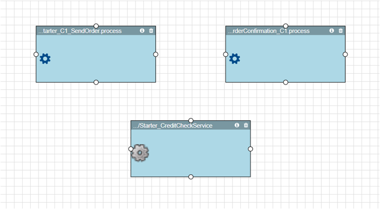
Create the relationship of the steps by dragging transitions between steps:
Configure the steps by pressing right mouse button over the step. Enter settings:
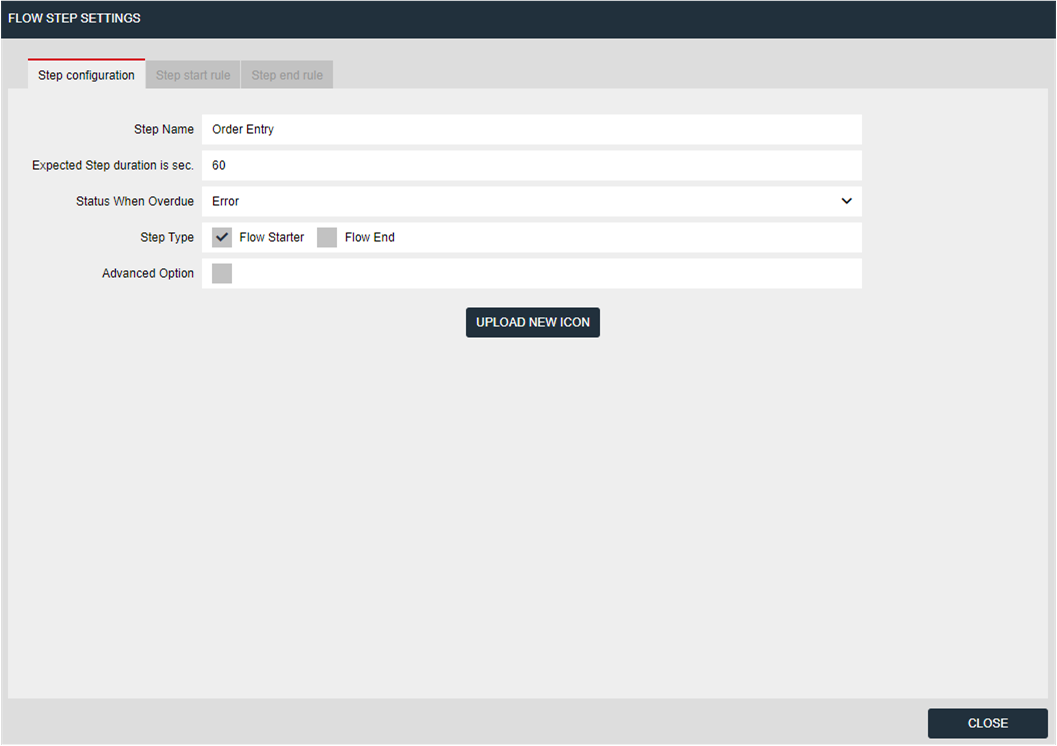
| Step name: | Enter a name of the step. By default it gets the name of the process |
|---|---|
| Expected Step duration in sec: | |
| Enter the expected duration of how long you think the step may take. Default is 60 secs. | |
| Status when override: | |
| Decide which status the step will get, when the step takes longer than expected | |
| Step type: | Specify whether the step starts a Flow (“Flow Starter”), or ends a Flow (“Flow End”) |
| Start rule: | Click ‘+’ to enter a rule for starting this step |
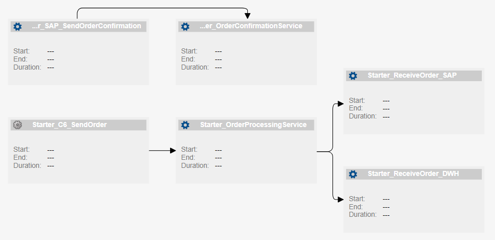
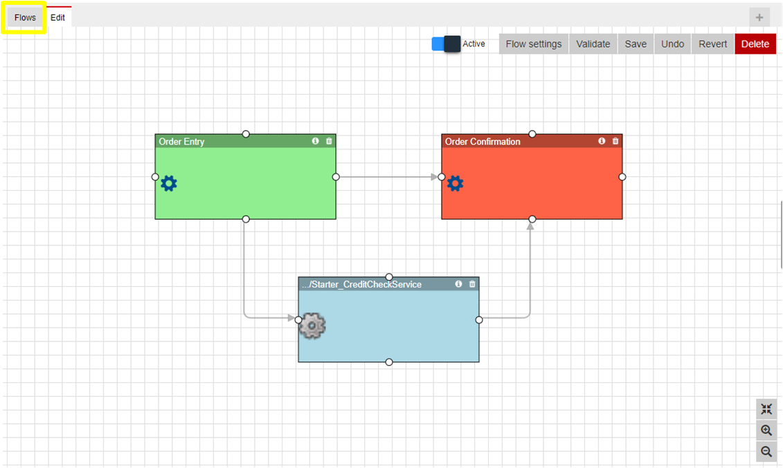
Let’s proceed accordingly with the other steps. The Flow will look as follows:
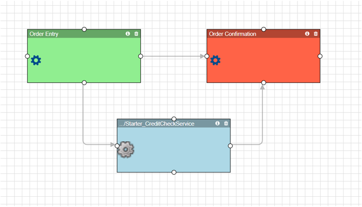
A Flow Starter gets a green background color, a Flow End is indicated by red color.
Now the Flow settings can be configured:
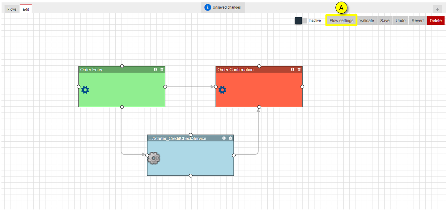
- Click on “Flow Settings”
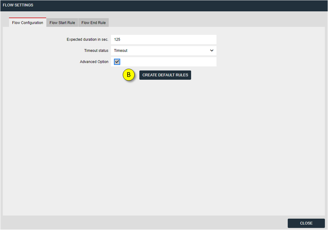
- Clicking on this button will create default rules for the Flow based on the characteristics of the correlation of the process instances
Click on “Flow Start Rule” and check the automatically generated rules.
Flow Start Rule:
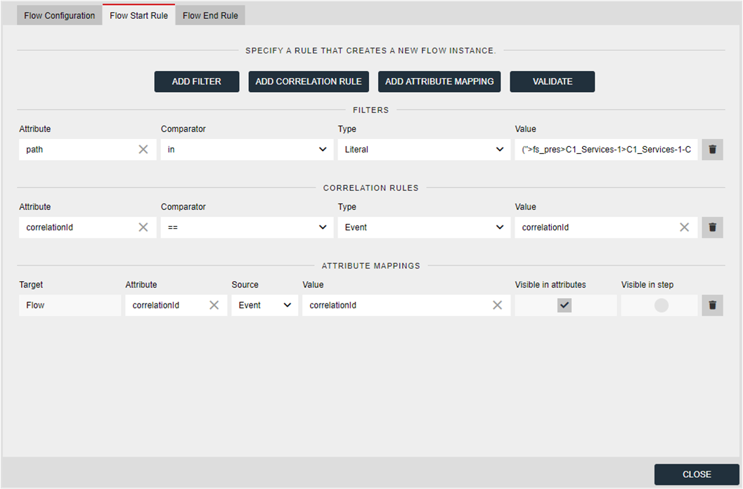
| Filters: | Condition checks, if the attribute “path” matches the given process name |
|---|---|
| Correlation rules: | |
| This is the correlation criteria. Condition check, if correlationId is matching. | |
| Attribute mappings: | |
| The mapping creates a Flow attribute “correlationId” that is mapped from an event attribute with the same name. A mapping allows you to access content on Flow level that has its source from event message. | |
If all conditions match, a Flow instance is created.
Flow End Rule:
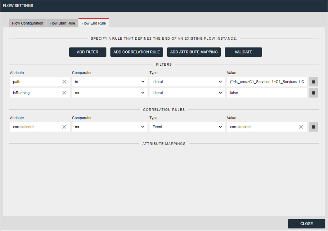
| Filters: | Condition checks, if the attribute “path” matches the given process name and the process is not still running. |
|---|---|
| Correlation rules: | |
| This is the correlation criteria. Condition check, if correlationId is matching. | |
If all conditions match, the Flow is ended.
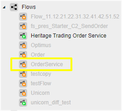
Click on SAVE to save the Flow model:

Once you saved the Flow model, a new Flow element will be added to the Tree:
Add rules to the Flow model
You can add additional rules for the Flow or any step, if required. In this example the default rules are sufficient.
Activate the Flow
The Flow is still inactive. You have to activate the Flow to start the rule set of the Flow and its steps.
Select the Flow from Tree and click on activation button:

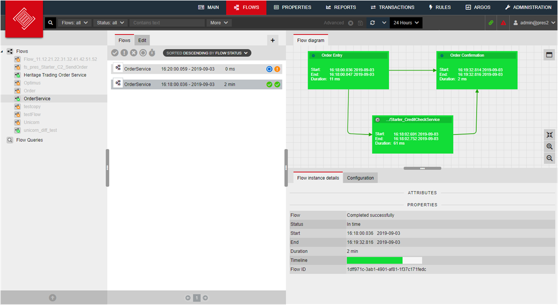
See Flow instances
An activated Flow rule set will create Flow instances, as soon as events are received that match to the rules. In order to see these Flow instances you have to switch from design view to runtime view.
Click on the button “Flows” to switch to runtime view:
You will now directed to the runtime view: